Description
The shell and tube heat exchanger is commonly used in the food and chemical process industries. This type of exchanger consists of a number of tubes in parallel enclosed in a cylindrical shell.
Heat is transferred between one fluid flowing through the tubes and another fluid flowing through the cylindrical shell around the tubes.
The miniature exchanger supplied is designed to demonstrate liquid to liquid heat transfer in a 1-7 shell and tube heat exchanger (one shell and seven tubes with two transverse baffles in the shell).
Features & Benefits
-
A miniature shell and tube heat exchanger for use with an Armfield Computer Controlled Heat Exchanger Service Unit
-
Comprises an outer shell and seven internal tubes. There are two transverse baffles inside the shell
-
The heat exchanger is constructed from stainless steel tube and clear acrylic. It is mounted on a PVC baseplate which is designed to be installed on the plinth of the Heat Exchanger Service Unit without the need for tools
-
The stainless steel tubes can be removed from the heat exchanger for cleaning
-
A comprehensive instruction manual is included
ArmBUS software Features
ArmBUS software is provided as standard with the HT30X for all the Armfield heat exchanger accessories. Individual programs are provided for each exchanger, and each program contains a selection of separate exercises that can be performed.
The actual details are exercise specific, but typically the following interfaces are available:
-
Full Graphical User Interface (GUI) for each experiment with display screens tailored for each exercise
-
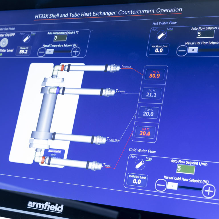
All the temperatures and flow rates are displayed on a diagrammatic representation of the equipment
-
Student questions and equations can be accessed individually for each exercise
-
The hot-water flow rate utilises optional Manual/Automatic control to control the pump output. Manual control allows the user to select a percentage of the total power to supply to the pump. Automatic control allows the user to input the desired set point which the PID control will reach and maintain. The use of automatic control ensures the flow is stable despite changes in the viscosity of the water due to heating
-
Real-time flow rate readings are displayed in L/min Sensor data is collated and calculations are displayed in a data-log, a tabulation function provided with the armBUS software. The data is in tabulated format and can be saved and accessed through a .csv file compatible with software such as Microsoft Excel
-
The cold-water flow control valve utilises optional Manual/Automatic settings to control water flow from the mains. Manual control allows the user to open/close the valve between 0 and 100%. Automatic control allows the user to input the desired set point which the PID control will reach and maintain so long as the input pressure is adequate.
-
The heater utilises optional Manual/Automatic control to supply power to the heater element in the boiler. Manual control allows the user to select a percentage of the total power to supply to the heater. Automatic control allows the user to select a set point (°C), and then PID control software heats the water to and maintains a set temperature
-
The data from the sensors is plotted and displayed in a user-configurable graphing function of the software. It can be displayed separately from the data logging and each sensor output can be viewed independently
-
Processing of measured values to obtain calculated results (this can be linked to the questions and answers to ensure student understanding, answers to equation calculations can be found as part of the datalogger output)

 Enquiry:hkmarketing@epc.com.hk
  Whatsapp Enquiry: +85261990717


